
Project 3
Platformer


Build a remotely controlled vehicle that can cross progressively wider gaps using the provided radio hardware and Pi Pico controller.
Overview
The Platformer project requires teams to design and build a remotely controlled vehicle capable of crossing gaps. Each system must use the provided radio frequency module and Pi Pico controller for control. Test runs may begin with a 10 cm setup gap, but scoring starts at 20 cm and then increases in 10 cm increments after each successful crossing until the vehicle fails. Teams are scored based on the longest gap their vehicle successfully crosses, with the team achieving the greatest distance earning the most points.
The mechanical kit includes low-cost custom linear actuators for teams that want to build extending or lifting mechanisms. These actuators are provided as kits rather than finished units, so teams should expect some assembly work and may need to adapt or modify the supplied STL parts to suit their final design.
Objectives
- Design and build a vehicle capable of crossing the largest possible gap.
- Demonstrate reliable remote operation and stable vehicle control throughout each crossing attempt.
- Develop a robust mechanical system that can maintain performance as gap distance increases in 10cm increments.
- Achieve successful crossings efficiently, reliably and quickly.
- If two or more teams successfully cross the same maximum gap, the team with the fastest successful crossing at that distance will rank higher.
Quickstart
- Start with VS Code Setup, Pi Pico Controller, and Power & Wiring before you build a complex chassis.
- Prove the handheld controller and
nRF24L01+link first, then get one drive motor working cleanly through the motor driver. - Build the smallest stable vehicle that can steer, stop, and reverse before you add bridge or actuator mechanisms.
- Treat
20 cmas the first scored gap. Use shorter runs as setup and control checks only.
Materials Provided
| Item | Picture | Description |
|---|---|---|
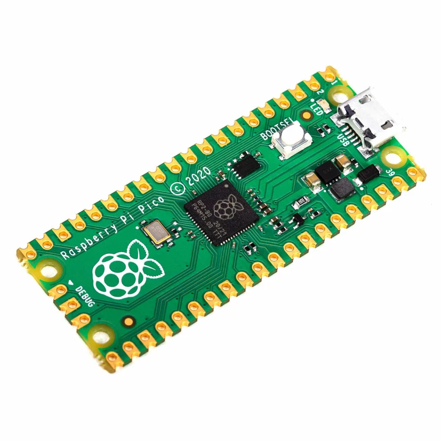
Raspberry Pi Pico microcontroller |
|
Primary controller board for the vehicle and handheld remote. Teams use it to read inputs, coordinate radio traffic, and drive the rest of the embedded system. |
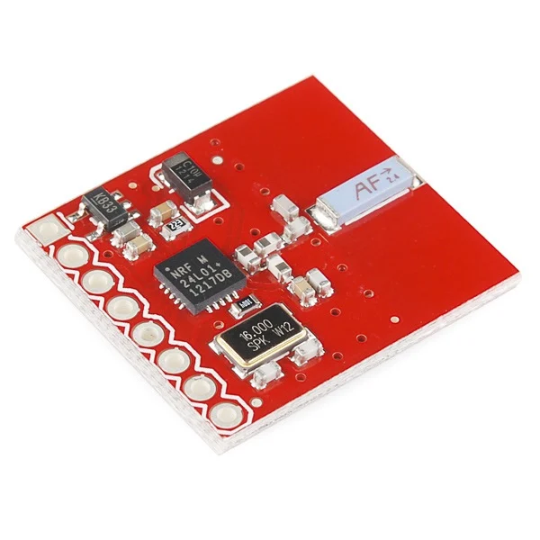
nRF24L01+ 2.4 GHz wireless transceiver modules |
|
Provides the required radio link between the operator controls and the gap-crossing vehicle. |
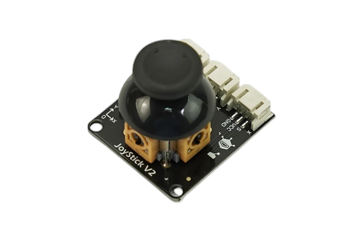
| Analog joystick modules |
|
Two-axis operator input for steering, speed control, and mechanism commands on the handheld controller. |
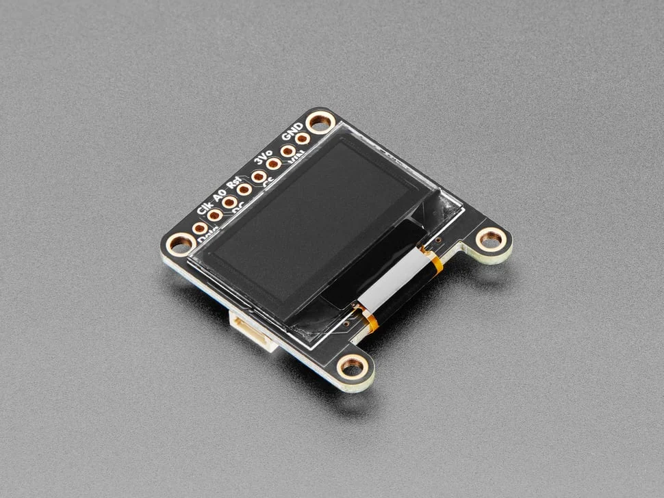
0.96" 128 x 64 OLED displays |
|
Useful for lightweight status output such as pairing state, battery checks, selected mode, or quick debug readouts. |
Drive components: N20 gear motors and TT motor wheel kits |
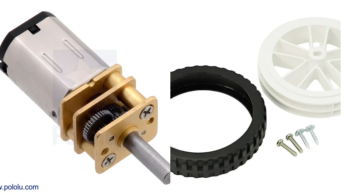
|
Mix of compact geared motors and wheel-drive parts for traction, chassis movement, and small powered mechanisms. |
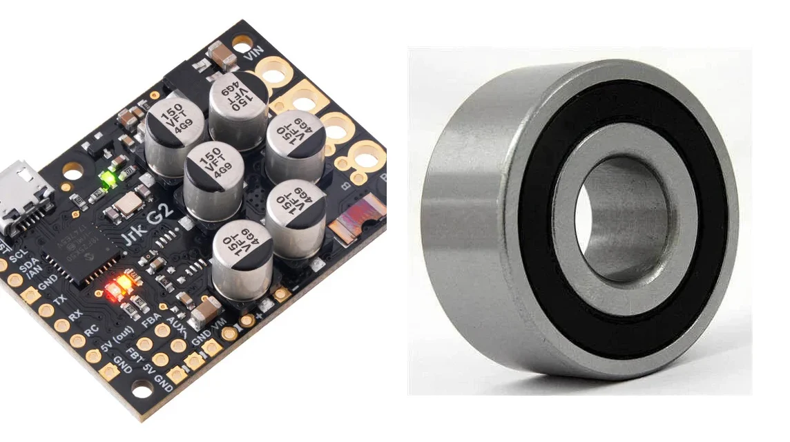
L298N dual H-bridge motor driver boards |
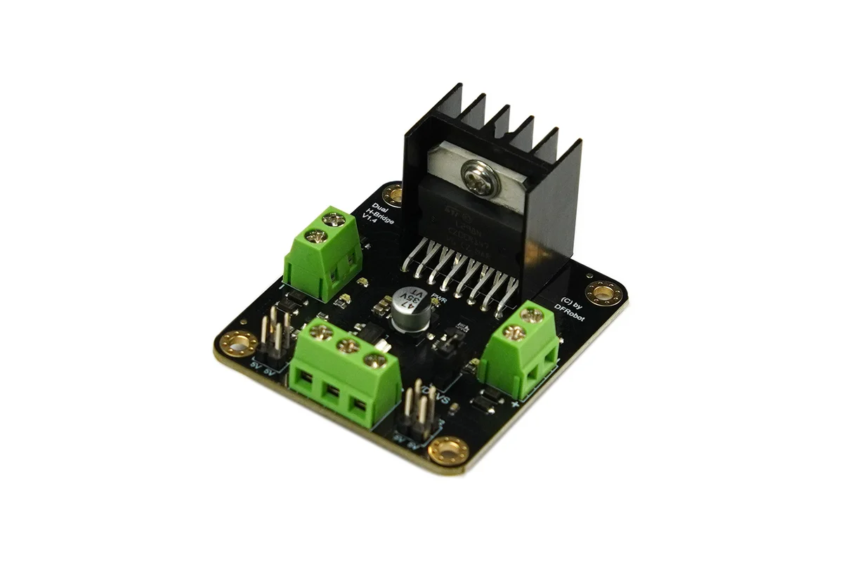
|
Lets the Pico reverse and control DC motors safely without driving the motor load directly from the microcontroller. |
LM2596 DC-DC voltage regulators |
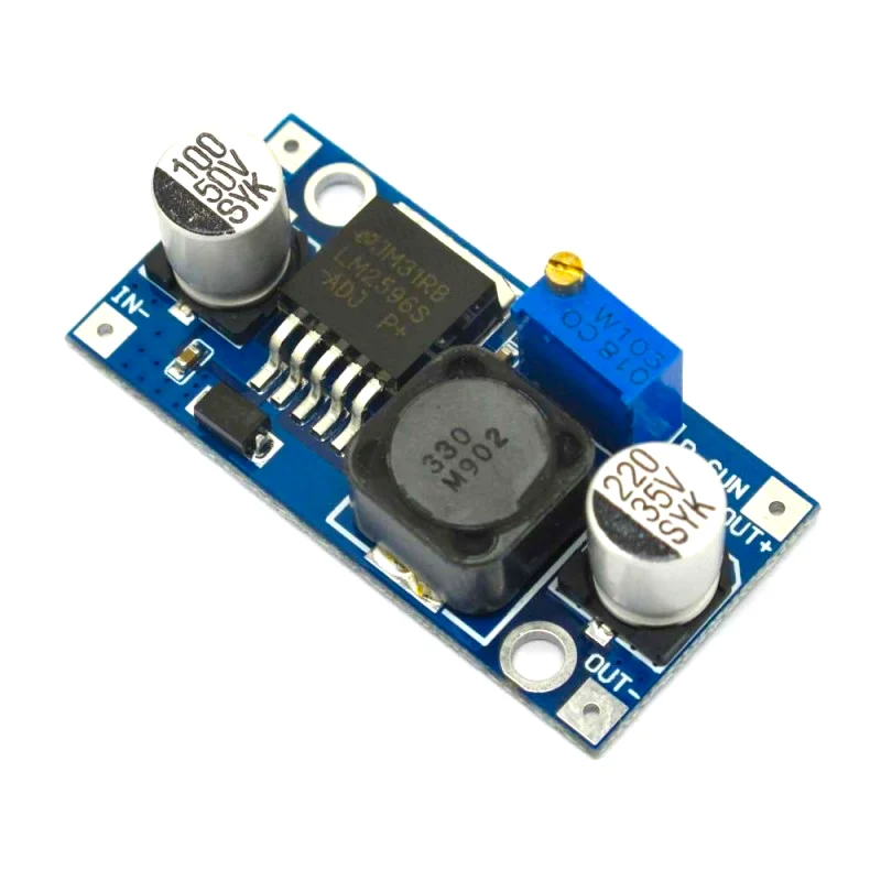
|
Adjustable buck regulators for stepping battery voltage down to cleaner supply rails for logic, radios, and accessories. |
| Custom linear actuator kits |
|
Low-cost extending actuator hardware for teams that want lifting or bridging mechanisms. The kits are supplied as parts, so expect assembly work and possible STL tweaks. |
Support hardware: casters and 694-2RS bearings |
|
Useful for rolling support points, pivots, and smoother contact surfaces where the chassis or bridge structure needs low-friction motion. |
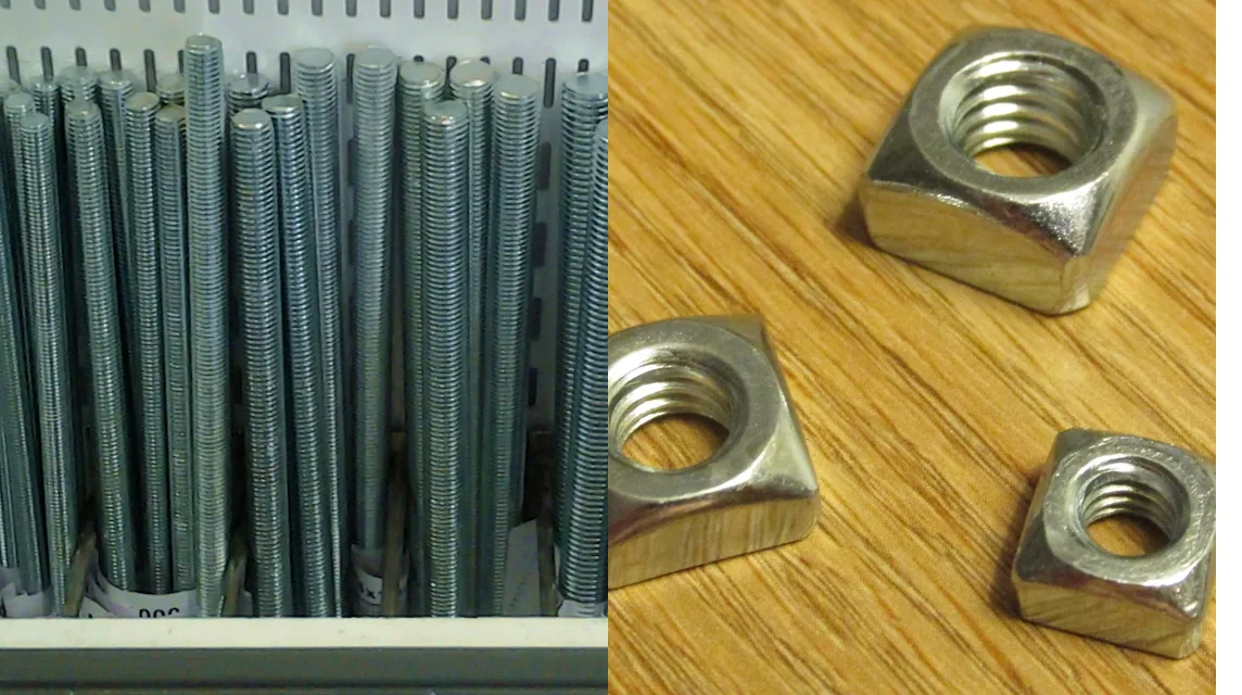
Mechanical hardware: M4 threaded rod and M4 square nuts |
|
General-purpose structural hardware for frames, adjustments, clamping, and custom linkage assemblies. |
Common Materials
- Battery supplies:
3xAAholders,6xAAholders, andAAalkaline batteries - Prototyping materials: perfboard and solderless breadboards
- Wiring supplies:
22 AWGelectrical wire and male-to-female Dupont jumper wires - General electronics assortment: resistors, capacitors, LEDs, diodes, and transistors
- Common fasteners:
M4nylon insert lock nuts andM3self-tapping screws - Basic assembly tools: precision screwdriver set
Mechanical Notes
- The actuator option is intended as a cheaper custom alternative to off-the-shelf linear actuators.
- Teams should expect to assemble the actuator kits before use.
- Some teams will likely need to adjust, remix, or reprint the supplied STL parts to fit their chassis or linkage geometry.
Common Failure Points
- building a large bridge or actuator system before the base drive works reliably
- debugging radio, motor driver, and power issues all at the same time
- leaving handheld controller bring-up until late in the build
- designing around one perfect crossing instead of a repeatable scored run
Actuator Reference Video
Custom linear actuator reference
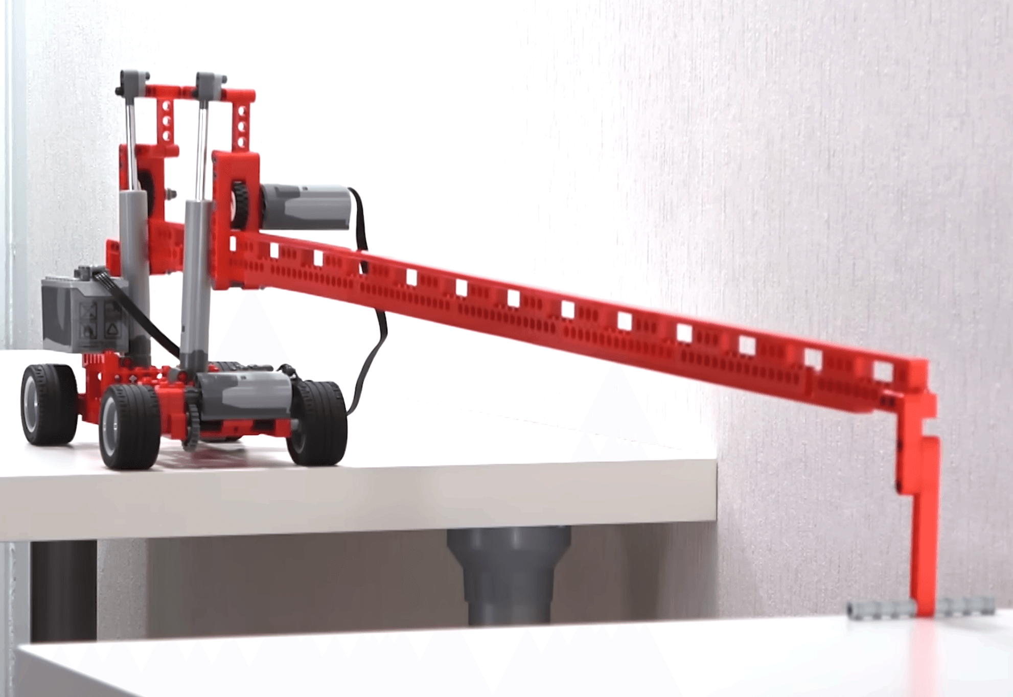
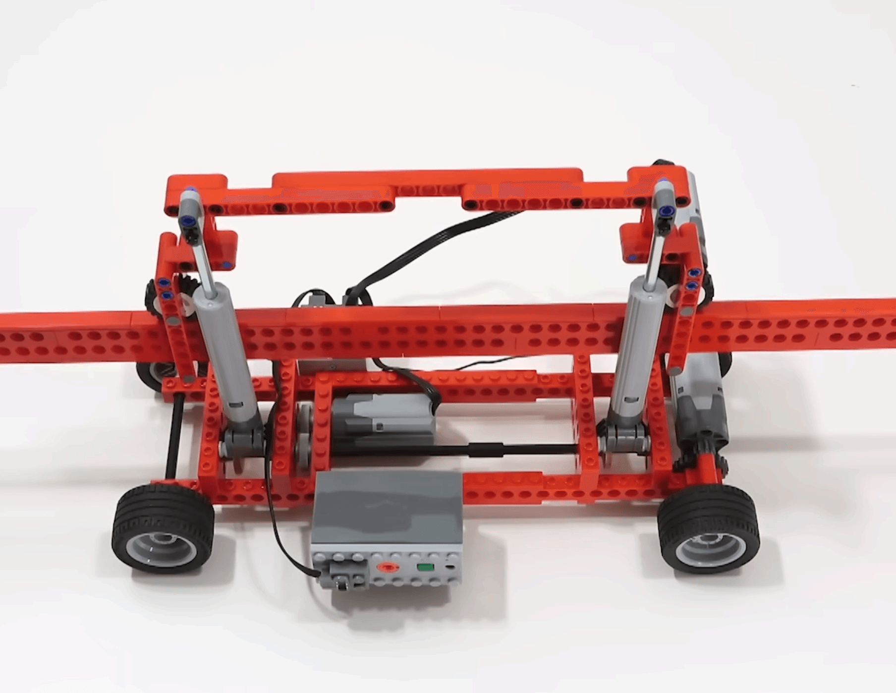
Open on YouTubeReference Builds
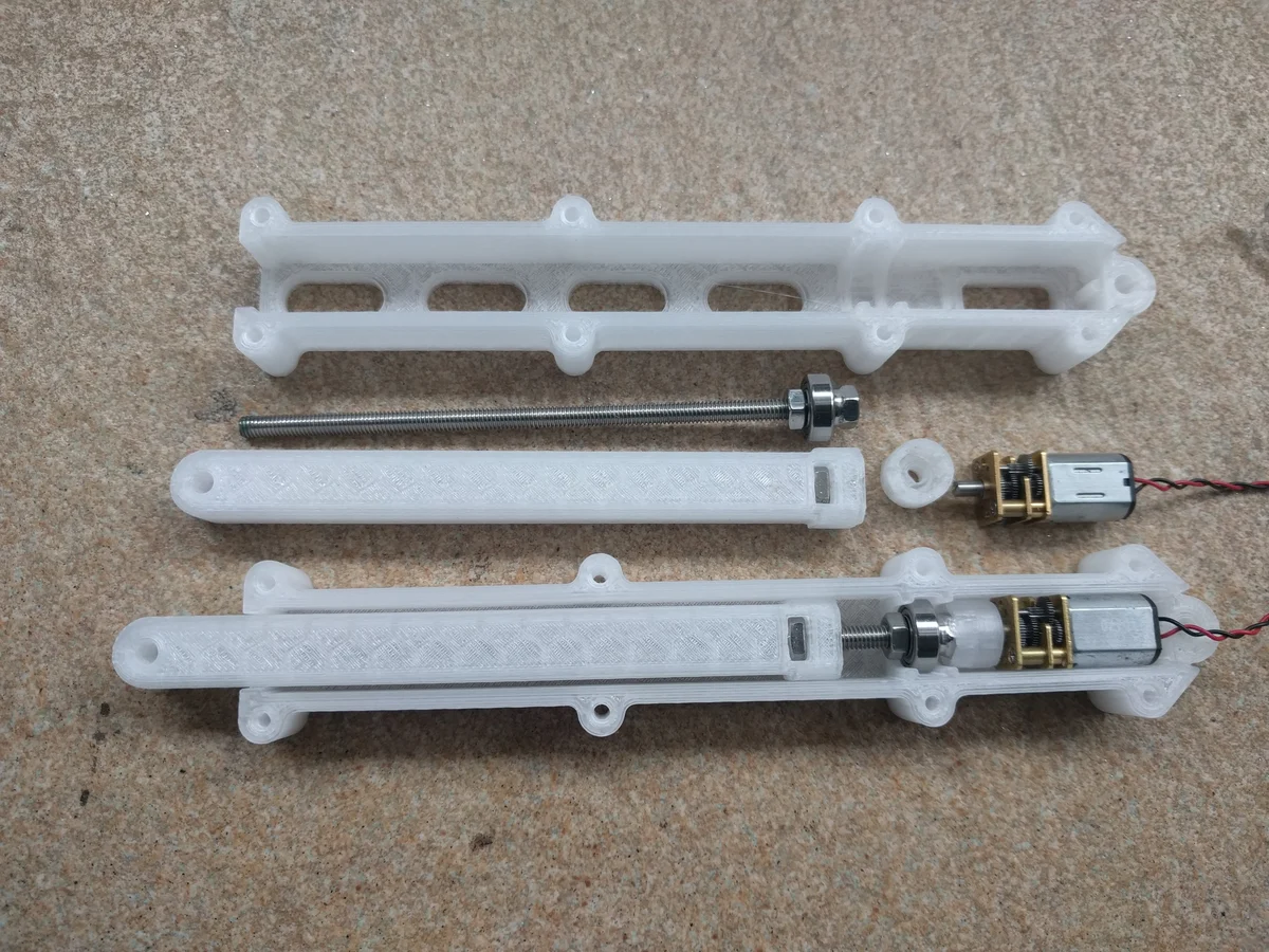
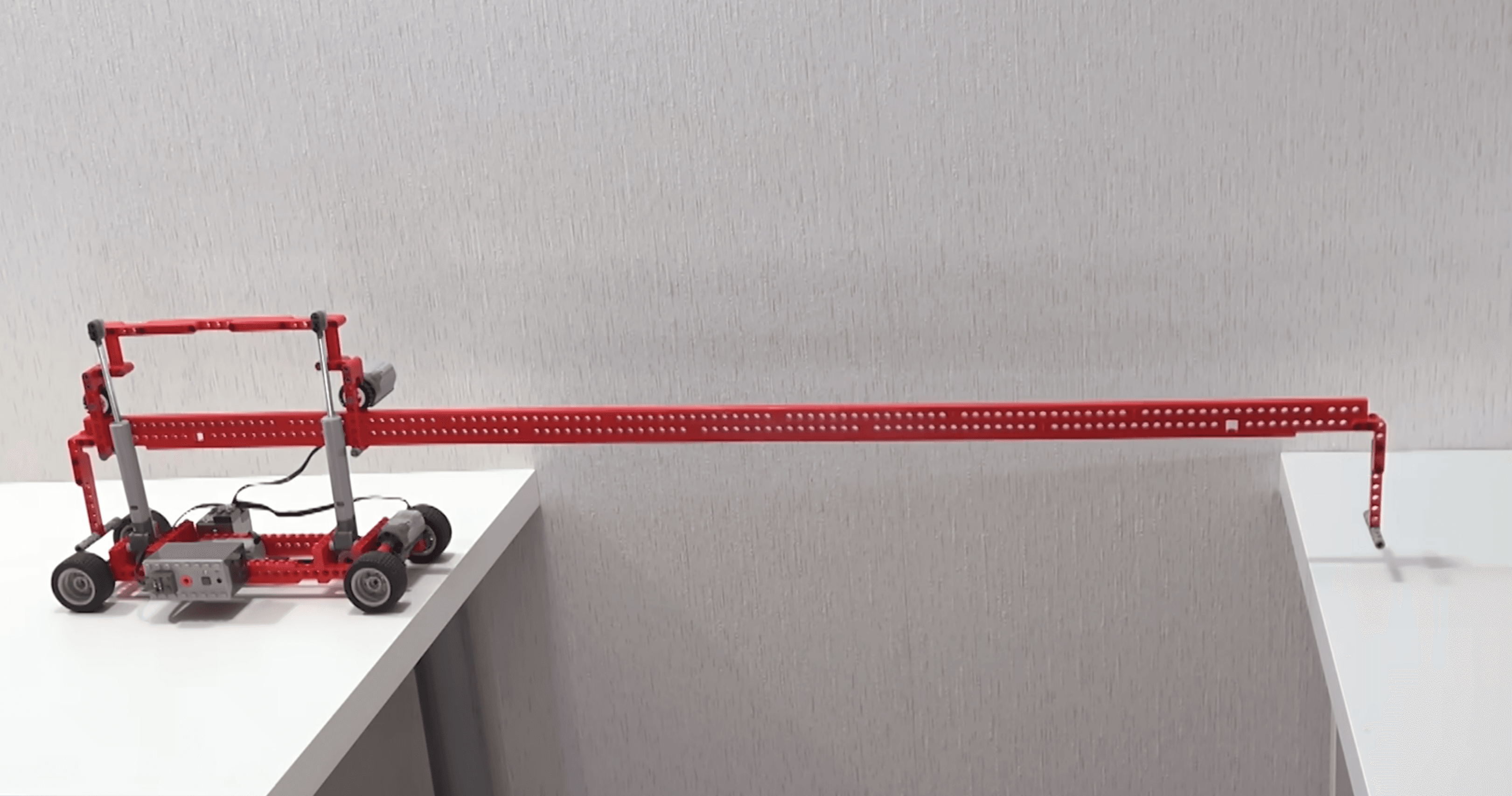
These stills show one example of how a long bridge arm and actuator-assisted chassis can be arranged. Use them as mechanism reference, not as a required final design.


Programming approach
VS Code is the primary recommended workflow for this project. Start with VS Code Setup, then use Pi Pico Controller for the organiser controller pin map and radio bring-up, and Power & Wiring before you power the full vehicle.
- Recommended path: VS Code
- MicroPython, Arduino IDE, or Thonny can still be used if your team already knows them, but treat them as secondary options
Scoring Criteria
Gap Crossed (60 points)
| Gap crossed | Points |
|---|---|
| 20 cm crossed | 4 points |
| 30 cm crossed | 6 points |
| 40 cm crossed | 7 points |
| 50 cm crossed | 8 points |
| 60 cm crossed | 9 points |
| 70 cm crossed | 11 points |
| Highest successful gap | 15 points |
Crossing Speed (20 points)
Speed points are awarded by speed placement at the team’s highest successful gap, with 1st being the fastest successful crossing at that distance. The points are distributed to create stronger separation near the top while still ensuring every successful team receives some speed points.
Top 10:
| Rank | Points |
|---|---|
| 1st | 20 |
| 2nd | 18 |
| 3rd | 17 |
| 4th | 15 |
| 5th | 13 |
| 6th | 12 |
| 7th | 10 |
| 8th | 9 |
| 9th | 8 |
| 10th | 7 |
Reliability and Repeatability (10 points)
| Category | Points |
|---|---|
| Smoothness | 4 points |
| Control | 3 points |
| Repeatability | 3 points |
Engineering Design (10 points)
Teams start with 10 points. Points are deducted for weaknesses in mechanical design, electrical design, system integration, and overall build quality.